Don't Route Over Ground Plane Splits — Part 5: Compliance
Took the same three boards to an accredited EMC lab. The split board fails Class B by 26.8 dB. The stitching caps recover 25 dB but still fail by 1.8 dB. Only the intact plane passes.
Pre-compliance walks into a chamber
Part 1 and Part 2 measured the boards on the bench in a TEM cell. Part 3 and Part 4 mapped the field above them with a near-field scanner. Four parts of measurements told a clear story: the split board radiates a lot more than the intact one, and stitching caps recover most of the damage.
That was pre-compliance. Fast, repeatable, and ultimately an educated guess at what the chamber would say. So I took the same three boards to an accredited EMC lab and put them in front of the actual regulatory limit. The chamber does not read bench data.
The chamber
Thanks to EMV Rhein Neckar for letting me use the chamber in the name of science.
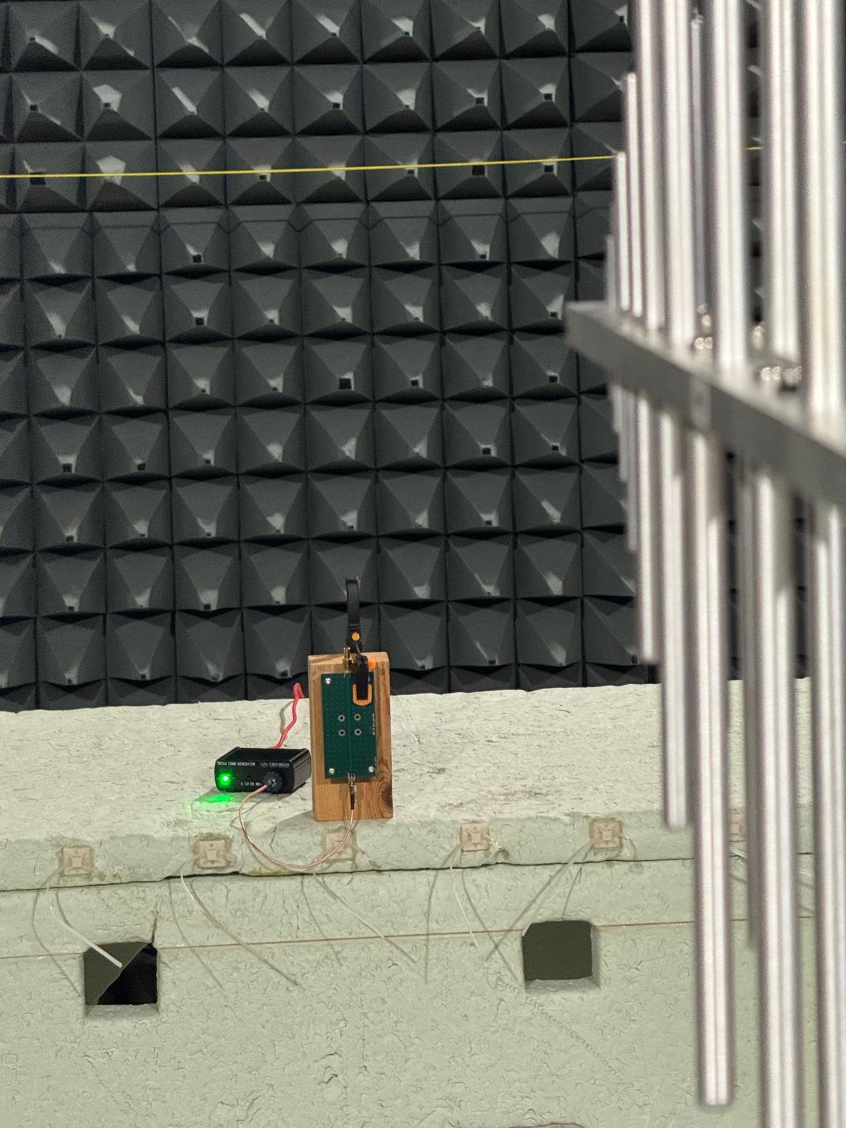
The setup:
- Receiver: Rohde & Schwarz ESR-7, 30 MHz–1 GHz scan, RBW 120 kHz, QP and Average detectors.
- Antenna: BiLog broadband antenna with FAR transducer correction. This is EMVRN's standard antenna for CISPR 16-2-3 radiated emissions across 30 MHz to 1 GHz.
- Chamber: 3 m absorber chamber configured as a fully anechoic room, with a 1.5 m turntable rated to 300 kg. Vertical polarization, 0° azimuth.
- Source: same Tekbox TBCG4 comb generator from Part 1, driving the SMA input.
- Limit: EN 55032 Class B 3 m FAR. The line you have to stay under to sell an ITE product into a residential environment.
- Lab: EMV Rhein-Neckar GmbH, DAkkS-accredited per DIN EN ISO/IEC 17025:2018 (D-PL-19334-01-01).
One detail to set expectations: this is comparative chamber data, not a full Class B compliance scan. A formal compliance test rotates the turntable through 360° in both polarizations and reports the worst case. We measured one polarization at one azimuth, identical for all three boards. That is enough to compare them honestly against each other and against the limit. It is not enough to certify a product. And the boards themselves are not really products: just a four-layer microstrip with a single trace into a 50 Ω terminator. But they radiate like one.
The verdict
All three boards on the same axes, with the EN 55032 Class B QP limit drawn on top. The solid lines are smoothed envelopes that follow the peak tops of each trace. You can toggle the raw spectrum data on if you want to see the actual comb harmonics. Hover for readout values at any frequency.
Peak QP envelope across the band, against the EN 55032 Class B 3 m FAR limit:
| Board | QP envelope peak | At | Margin to limit |
|---|---|---|---|
| Good (intact plane) | 37.4 dBµV/m | 890 MHz | −4.6 dB |
| Bad + stitching caps | 43.8 dBµV/m | 890 MHz | +1.8 dB |
| Bad (split, unmitigated) | 68.8 dBµV/m | 850 MHz | +26.8 dB |
Receiver screenshots. Green is the QP detector, orange is the Average detector, the red dashed line is the Class B 3 m FAR limit.
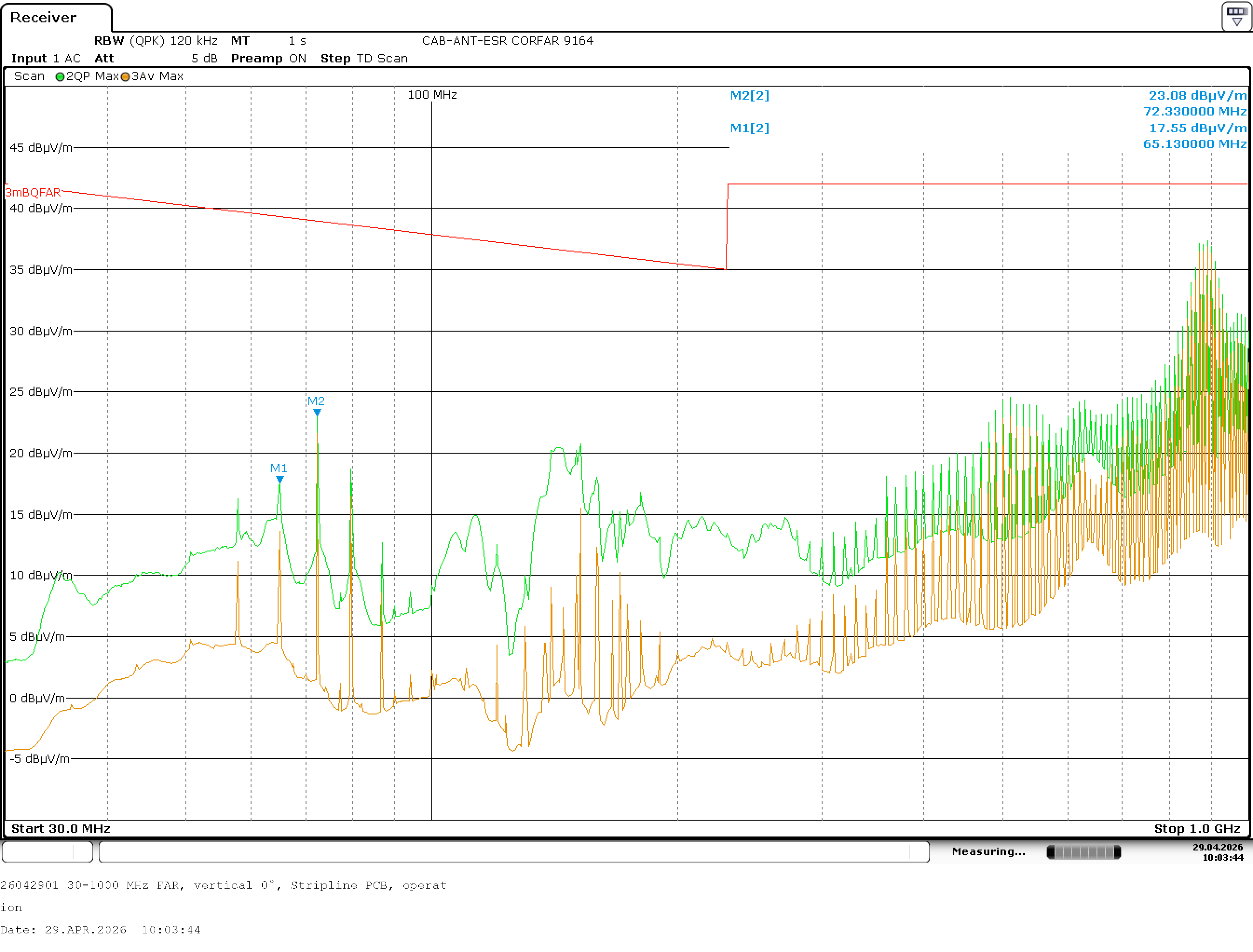
The good board stays under the limit across the entire band. The QP envelope reaches 37.4 dBµV/m at 890 MHz, with about 5 dB of margin to the limit. Below 230 MHz the limit slope is wider but the trace is also lower. Comfortable pass.
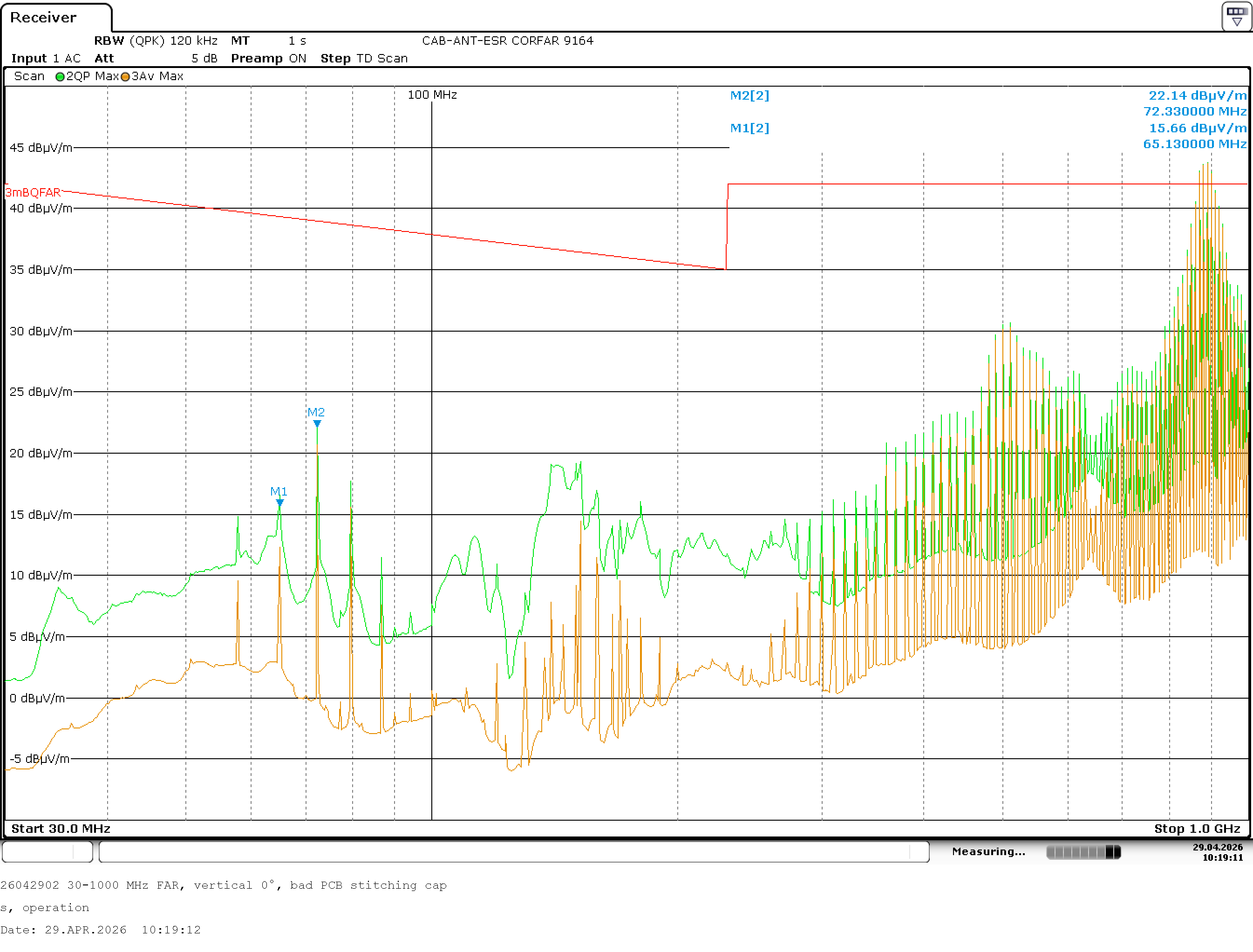
Same axes and scale as the good board. The caps recovered most of the broken-return-path radiation, but the QP envelope crosses the limit at the high-frequency end. Worst peak is 43.8 dBµV/m at 890 MHz, 1.8 dB over.
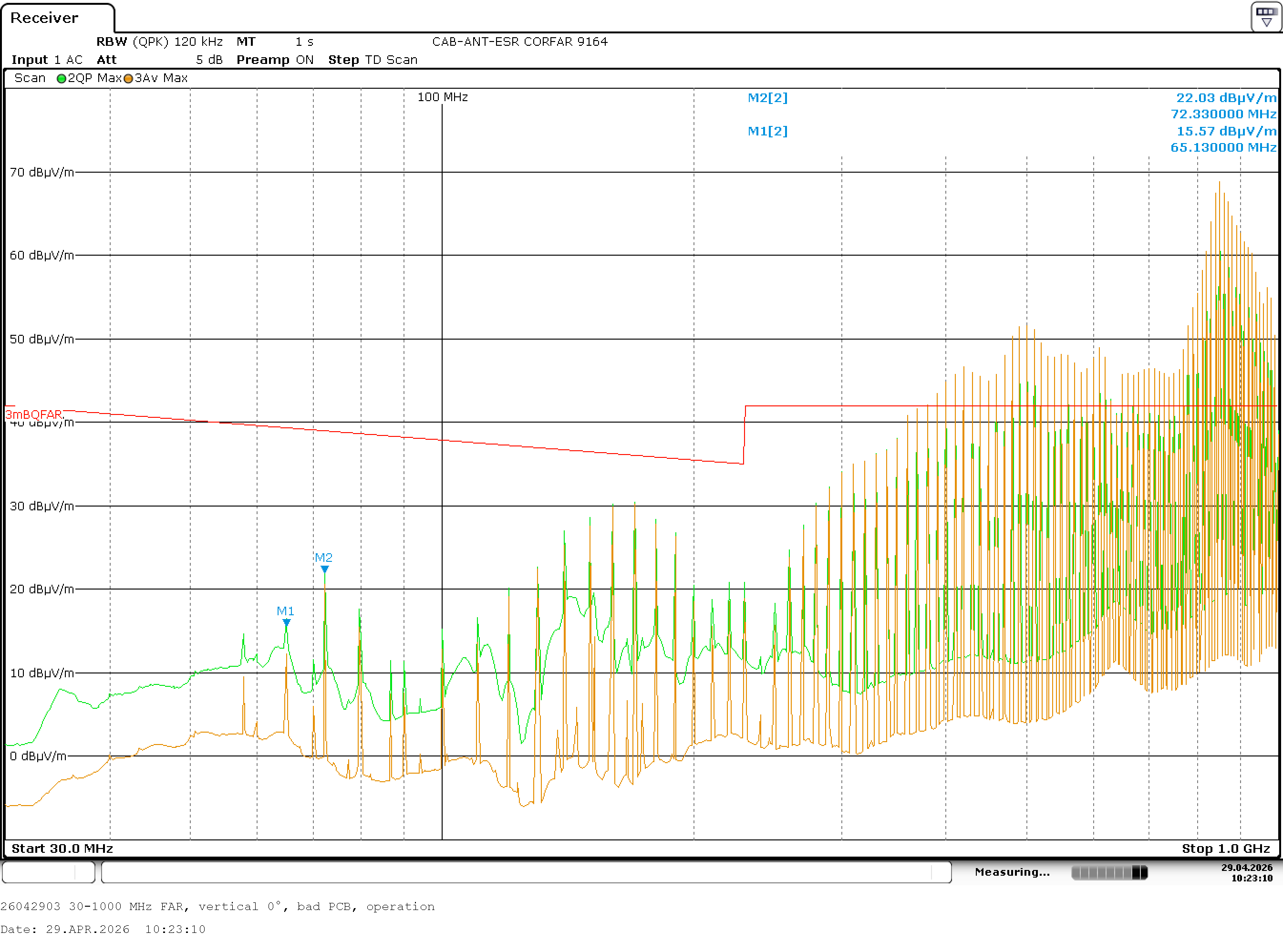
The y-axis had to be re-scaled to 70 dBµV/m to fit the trace at all. The limit line sits roughly mid-screen, and the comb harmonics tower over it from 700 MHz upward. Worst peak is 68.8 dBµV/m at 850 MHz, 26.8 dB over Class B.
What the chamber confirms
Below 230 MHz, all three boards behave roughly the same. The slot is not yet long enough to be an efficient antenna at those wavelengths, so the broken return path does not radiate much. Everyone passes.
Above 700 MHz, the split board falls apart. Peaks reach 68.8 dBµV/m against a 42 dBµV/m limit. 26.8 dB over Class B. You don't fix that with a ferrite or a bypass change. The layout has to come apart. More than twenty times the field strength of the regulatory ceiling, on a board that is otherwise mechanically and electrically identical to the one beside it on the bench. The split board is, by accident, a small antenna at 850 MHz.
The caps board sits between the two, as Part 4's near-field terrain predicted. Two 100 nF 0603 capacitors across the slot recover about 25 dB at the worst peak. The QP envelope still ends up at 43.8 dBµV/m against a 42 dBµV/m limit. 1.8 dB over Class B. Caps recovered most of the damage. Not all of it.
What you take home
- Pre-compliance worked. The TEM-cell deltas in Part 1 were not theatrics; they were a real warning. The bench predicted the chamber.
- The split is unforgiving above 700 MHz. When the slot length lines up with the wavelength, it stops being a parasitic and starts being an antenna.
- Stitching caps reduce, but do not rescue. ~25 dB of recovery from two 100 nF 0603s is real, and useful, and still not enough to pass Class B on this board. The intact plane is the only one that passes.
- The fastest fix is not splitting the plane. If you can avoid the split, avoid it. If you cannot, stitch it, verify, and expect to pay margin you may not get back.
This closes the saga. Five parts: bench emissions, bench immunity, near-field heatmap, near-field 3D terrain, and a real chamber. The boards behaved exactly like the rule says they should. Knowing it before the layout costs nothing. Finding out after costs 27 dB. And a lab visit.
Don't route over ground plane splits.